PLC Control
An external operation panel is required when the customer needs to control template switching signals via PLC. If no external panel is needed, see PC Control.
Panel Introduction
The signal switching board consists of two parts: input signal and transfer signal.
V2301
Input Signal
Composed of two groups of 10 green connectors, responsible for converting given input information. This module requires separate power supply, typically using the positive/negative terminals on the right side (board edge).
After powering, test with a wire: connect one end to ground, the other end to the desired file number to input the signal.
⚠️ Important: Never connect the other end to power — this will cause a short circuit!
Transfer Signal
Located on the opposite side from the connector group; no separate power needed, powered by the mainboard. Connect to the mainboard with five wires (same pin order). The mainboard serial port has “串口” printed; the corresponding pin on the signal switching board has a right-angle 「 marking, also ground — use this to determine orientation.
V2401 / V2402
There are two transfer module variants for different mainboard types. The main difference is whether the mainboard can power the transfer module:
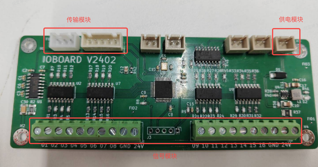
- No power supply: use the left module (third from left is ground; connect the right-side fifth pin separately)
- With power supply: use the right module
Switching Logic
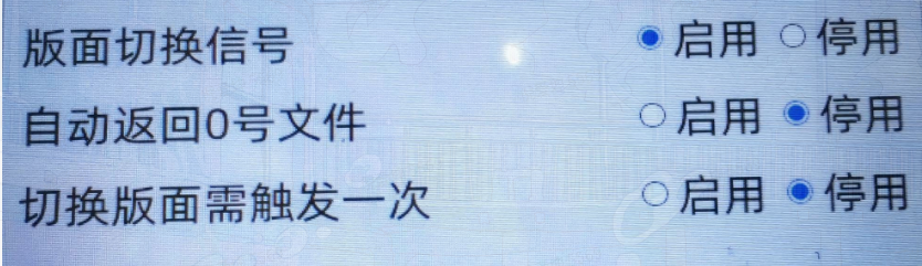
The layout switch signal enables the switching function. If switching does not respond, re-enable it here or restart the software.
The usage methods are formed by combinations of Auto return to file 0 and Require one trigger to switch. The precondition is that files with the corresponding numbers are stored; otherwise switching has no effect.
1. Neither enabled
When a new file number is entered, switching occurs immediately — in both printing and editing states. It stays until a new file number is entered or manually changed.
2. Only auto return to file 0
The key requires long press. While held, the layout switches to the held file number; on release, it returns to the configured file 0. Create file 0 in advance.
3. Only require one trigger to switch
In printing state, the previous layout must be triggered at least once before switching to a new layout. Subsequent switches also require a trigger.
4. Both enabled
No long press needed. In printing state, file 0 is the continuously printed file. When a new file number is pressed, the layout switches to that file; after one successful print, it automatically returns to file 0.
Notes
- With “require one trigger to switch” enabled, even the initial file 0 needs one print trigger before switching
- Avoid entering a new file number before the previous print has returned to file 0 — this can cause data loss
Packaging Notes
Old mainboards have no pull-up on the interrupt pin; floating state triggers frequent interrupts. This feature requires a new core board with interrupt triggering enabled.
Limitations
- Only supports local templates
- Only supports file names 1~14