Serial Communication
Hardware Setup
- Solder a second serial port on the development board
- Four female-to-female jumper wires
- RS232-to-serial data cable / male-to-male RS232 data cable
- TTL-to-RS232 chip
Wiring notes: Connect the development board to the chip with jumper wires. The short side of the board has “串口” (Serial) printed on it; on the serial side, the topmost pin is ground, the third pin from top is power, and pins 2 & 4 are data lines. If the test fails, swap the two data lines.
- Connect the chip to the PC / scale via the data cable
Serial Parameter Configuration
Before communication, confirm the serial parameters of the scale (or host) match the development board:
- Baud rate
- Data bits
- Parity
- Stop bits
In the board’s Settings → Hardware Settings, select Serial as the communication method and configure the parameters.
Data Exchange Examples
- Configure serial parameters on the board, load and enable the corresponding Lua script
- Insert the corresponding register into the text/barcode object
- Host sends data frames ending with
\r\n - When data reaches the register, the canvas object content updates
Scale Integration
- Configure baud rate and protocol on the scale — must match the board’s serial configuration



- Enable the weight acquisition script (e.g.,
getWeight.lua); if not present, install it from a USB drive
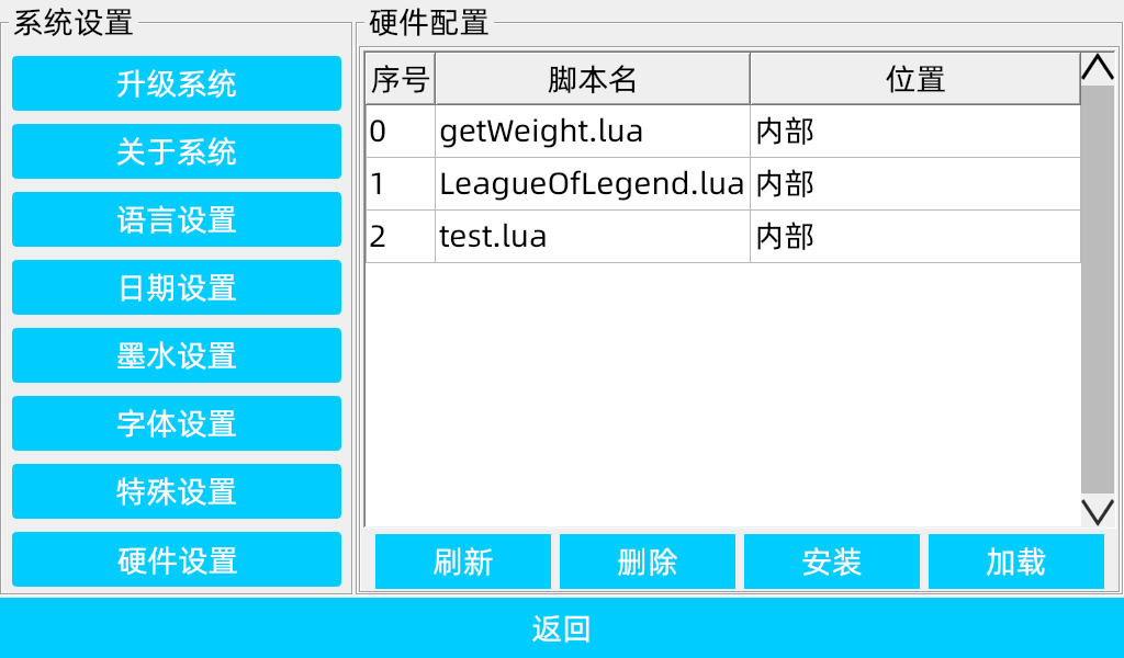
- Determine the register number and insert it into the text/barcode object
- When the weight data arrives, the object content changes — success
PC Integration
- Download software that supports serial data transfer (e.g.,
Bittlyon Linux)
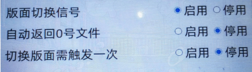
- Set serial protocol, PC serial port, and baud rate; then configure data bits, parity, stop bits
- Send text content ending with
\r\n; objects bound to registers update - After enabling the print feedback feature, a frame ending with
\r\ncontaining the print counter is returned after each print